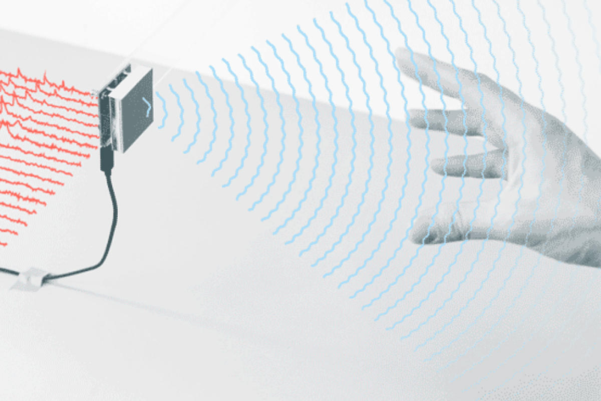
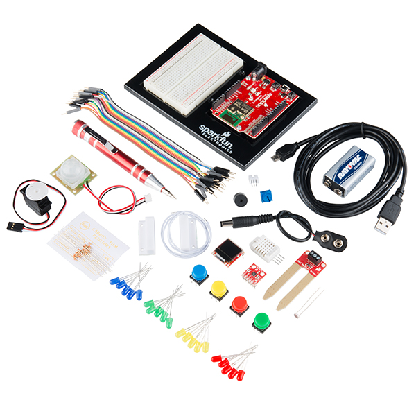
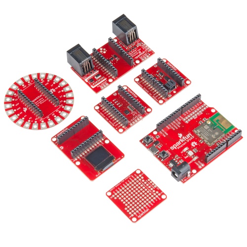
How to use Processing in Android mode with the IOIO board
March 04, 2012
A little while ago I was asked whether it would be possible to control hardware from a phone with the IOIO board from code written in Processing’s Android mode. Turns out you can – making it quite easy to develop Android apps that can control hardware in the real world – which is awesome. I didn’t find documentation on how to do this elsewhere online, so I thought I should post the gist of it here for posterity.
This is the IOIO board:
1. Download and install the Android SDK. This link will send you to the download page, which also has a guide worth reading.
2. Download and install Processing 2.0a4 or later (or the latest version – alpha releases are coming pretty frequently) – support for Android in Processing 1.5.1 no longer works.
2.5. Before trying anything with the IOIO board, you may want to make sure that Processing in Android mode works – plenty can go wrong just getting this set up. I highly recommend reading the Processing in Android wiki page (if you haven’t already) before going too far.
3. Download this version (ioio.zip) of Ytai’s IOIO library (equivalent to 3.11), exported in .jar format for use in Processing.
4. Unzip ioio.zip and install it as you would a Processing library (inside a folder called ‘libraries’ in your Processing sketch folder).
5. Open processing – You should see ‘ioio’ as an option under the ‘sketch’ -> ‘import library’ option
6. The import statements should like this:
import ioio.lib.util.*;
import ioio.lib.impl.*;
import ioio.lib.api.*;
import ioio.lib.api.exception.*;7. Go here: http://code.google.com/p/apwidgets/downloads/list and download the latest (and awesome!) APWidgets library, and put it in the same libraries folder that you put the ioio library. (this is optional, but if you want any GUI elements like the buttons or checkboxes used in the examples below, you’ll want it).
8. There are a few basic things to remember when doing Android development in Processing for the IOIO board.
- EVERY sketch you write for the IOIO board needs to have ‘internet’ permissions. To enable this, go to the ‘Android’ menu in Processing, select ‘Sketch Permissions’, and scroll down until you see the ‘INTERNET’ checkbox, check it, and save.
- Theory wise, the IOIO functions need to be put in their own thread – if you’re not familiar with threads in Processing, this post from Dan Shiffman is a great place to start.
- Usage of basic functions from the IOIO library is exactly as it appears in most of Ytai’s examples, but examples (like his HelloIOIO example) that use the AbstractIOIOActivity don’t work. That’s because we can’t make or use a separate Android activity straight from Processing.
/* IOIO Test 2 -
* Toggling the onboard LED on the IOIO board and changing rectangle size through Processing in Android mode
* by Ben Leduc-Mills
* This code is Beerware - feel free to reuse and credit me, and if it helped you out and we meet someday, buy me a beer.
*/
//import apwdidgets
import apwidgets.*;
//import ioio
import ioio.lib.util.*;
import ioio.lib.impl.*;
import ioio.lib.api.*;
import ioio.lib.api.exception.*;
//make a widget container and a button
APWidgetContainer widgetContainer;
APButton button1;
//our rectangle size
int rectSize = 100;
//boolean to turn the light on or off
boolean lightOn = false;
//create a IOIO instance
IOIO ioio = IOIOFactory.create();
//create a thread for our IOIO code
myIOIOThread thread1;
void setup() {
//instantiate our thread
thread1 = new myIOIOThread("thread1", 100);
//start our thread
thread1.start();
size(480, 800);
smooth();
noStroke();
fill(255);
rectMode(CENTER); //This sets all rectangles to draw from the center point
//create new container for widgets
widgetContainer = new APWidgetContainer(this);
//create new button from x- and y-pos. and label. size determined by text content
button1 = new APButton(10, 10, "Toggle LED");
//place button in container
widgetContainer.addWidget(button1);
}
void draw() {
background(#FF9900);
rect(width/2, height/2, rectSize, rectSize);
}
//onClickWidget is called when a widget is clicked/touched
void onClickWidget(APWidget widget) {
if (widget == button1) { //if it was button1 that was clicked
//rectSize = 100; //set the smaller size
if (lightOn == true) {
lightOn = false;
rectSize = 50;
}
else if (lightOn == false) {
lightOn = true;
rectSize = 100;
}
}
}/* This is our thread class, it's a subclass of the standard thread class that comes with Processing
* we're not really doing anything dramatic, just using the start and run methods to control our interactions with the IOIO board
*/
class myIOIOThread extends Thread {
boolean running; //is our thread running?
String id; //in case we want to name our thread
int wait; //how often our thread should run
DigitalOutput led; //DigitalOutput type for the onboard led
int count; //if we wanted our thread to timeout, we could put a counter on it, I don't use it in this sketch
//our constructor
myIOIOThread(String s, int w) {
id = s;
wait = w;
running = false;
count = 0;
}
//override the start method
void start() {
running = true;
//try connecting to the IOIO board, handle the case where we cannot or the connection is lost
try {
IOIOConnect(); //this function is down below and not part of the IOIO library
}
catch (ConnectionLostException e) {
}
//try setting our led pin to the onboard led, which has a constant 'LED_PIN' associated with it
try {
led = ioio.openDigitalOutput(IOIO.LED_PIN);
}
catch (ConnectionLostException e) {
}
//don't forget this
super.start();
}
//start automatically calls run for you
void run() {
//while our sketch is running, keep track of the lightOn boolean, and turn on or off the led accordingly
while (running) {
//count++;
//again, we have to catch a bad connection exception
try {
led.write(lightOn);
}
catch (ConnectionLostException e) {
}
try {
sleep((long)(wait));
}
catch (Exception e) {
}
}
}
//often we may want to quit or stop or thread, so I include this here but I'm not using it in this sketch
void quit() {
running = false;
ioio.disconnect();
interrupt();
}
//a simple little method to try connecting to the IOIO board
void IOIOConnect() throws ConnectionLostException {
try {
ioio.waitForConnect();
}
catch (IncompatibilityException e) {
}
}
}10. The code should compile both with an emulator and on the phone, though obviously it won’t work through the emulator. To send to the phone, plug your phone into the computer and select ‘sketch’ -> ‘run on device’. Processing should detect, install, and launch the sketch on your device. Yay!
11. After the sketch is installed on your phone, you’ll have to unplug it from your computer, and plug it into your IOIO board. Make SURE you have USB debugging activated. Your phone should give some indication that it has a USB connection when you plug it in.
12. You should see your sketch in along with the other apps – go ahead and launch it. The button should toggle on and off the yellow LED on the IOIO board. Success! (Note: If it doesn’t work, try relaunching the app a few times – this fixed things for me a few times, though your milage may vary.)
13. Example 2: Toggling a real LED, and changing the color of a rectangle based on analog values from a potentiometer.
For this to work, you’ll need an LED properly (e.g., with a resistor of appropriate value) hooked up to pin 3 of your IOIO board, and a trim pot (or other analog sensor) hooked up to pin 37.
Main Tab:
/* IOIO Test 4 -
* Toggling a real LED on pin 3, and reading values from a potentiometer on pin 37 through Processing in Android mode
* by Ben Leduc-Mills
* This code is Beerware - feel free to reuse and credit me, and if it helped you out and we meet someday, buy me a beer.
*/
import apwidgets.*;
import ioio.lib.util.*;
import ioio.lib.impl.*;
import ioio.lib.api.*;
import ioio.lib.api.exception.*;
APWidgetContainer widgetContainer;
APButton button1;
int rectSize = 100;
boolean lightOn = false;
IOIO ioio = IOIOFactory.create();
myIOIOThread thread1;
void setup() {
thread1 = new myIOIOThread("thread1", 100);
thread1.start();
size(480, 800);
smooth();
noStroke();
fill(255);
rectMode(CENTER); //This sets all rectangles to draw from the center point
widgetContainer = new APWidgetContainer(this);
button1 = new APButton(10, 10, "Toggle LED");
widgetContainer.addWidget(button1); //place button in container
}
void draw() {
background(#FF9900);
//change the fill value based on the analog read of our potentiometer
fill(thread1.value * 100); //it's * 100 because we only get values from 0-1, so really this should be * 255, or use the map function
rect(width/2, height/2, rectSize, rectSize);
}
//onClickWidget is called when a widget is clicked/touched
void onClickWidget(APWidget widget) {
if (widget == button1) { //if it was button1 that was clicked
if (lightOn == true) {
lightOn = false;
rectSize = 50;
}
else if (lightOn == false) {
lightOn = true;
rectSize = 100;
}
}
}
And our IOIO thread, with some slight changes:
class myIOIOThread extends Thread {
boolean running;
String id;
int wait;
DigitalOutput led;
AnalogInput in;
int count;
int ledpin = 3; //pin for our led
int potpin = 37; // pin for our potentiometer
float value; //our analog values range from 0 to 1
myIOIOThread(String s, int w) {
id = s;
wait = w;
running = false;
count = 0;
}
void start() {
running = true;
try {
IOIOConnect();
}
catch (ConnectionLostException e) {
}
try {
led = ioio.openDigitalOutput(ledpin);
in = ioio.openAnalogInput(potpin);
}
catch (ConnectionLostException e) {
}
super.start();
}
void run() {
while (running) {
//count++;
try {
led.write(lightOn);
value = in.read();
}
catch (ConnectionLostException e) {
}
catch (InterruptedException e) {
}
try {
sleep((long)(wait));
}
catch (Exception e) {
}
}
}
void quit() {
running = false;
//led.close();
ioio.disconnect();
interrupt();
}
void IOIOConnect() throws ConnectionLostException {
try {
ioio.waitForConnect();
}
catch (IncompatibilityException e) {
}
}
}
14. Upload to your phone as before, hook up your phone to the IOIO board, and launch the app. The button should turn on and off the LED, and the trim pot should change the color of the rectangle in the middle of the screen. Huzzah!
Here are some pics: for the visual learners out there:
Comments (0) | More: Code
DangerShield VJDJ
December 30, 2011
Since I’ve been asked to teach a course on Processing at SparkFun Electronics using the Danger Shield, I thought I should whip up something extra to show them a few of the things I won’t have time to go over in class (in it’s only 1 day, mind you). So, I decided to do a little vj/dj control with the sliders and buttons on the Danger Shield, making use of the Video and Audio (Minim) libraries in Processing. The Video below has no sound, but I’ve just tied some audio samples to the buttons, turning them into sample triggers. The video manipulation is abased off code by my former teacher at ITP, Dan Shiffman, except I’ve changed and added a few things to change the shape and rotation of the pixels in accordance with the different sliders on the Danger Shield.
Code for the processing side of the VJDJ can be found here.
Comments (0) | More: Projects
Dangershield VJDJ Code
NOTE – this code is for Processing, but was written in Eclipse with the help of the wonderful Proclipsing plugin, so you may need to make some adjustments if you’re running it straight from the Processing IDE.
/*
* Danger Shield VJDJ
* Using the Danger Shield from SparkFun to do live Video and Audio manipulation
* by Ben Leduc-Mills - http://benatwork.cc
* video code based off code by Dan Shiffman - http://shiffman.net
* This code is public domain but you buy me a beer if you use this and we meet someday (Beerware license)
*/
import processing.core.PApplet;
import processing.serial.Serial;
import processing.video.*;
import ddf.minim.*;
public class DangerShieldAV extends PApplet {
Capture myCamera;
MovieMaker mm;
Minim minim;
AudioSample kick;
AudioSample snare;
Serial usbPort;
// Size of each cell in the grid
int cellSize = 20;
// Number of columns and rows in our system
int cols, rows;
//int[] sensors;
String[] sensors;
boolean firstContact = false;
int slider1, slider2, slider3;
int button1, button2, button3;
int photoCell;
public void setup() {
size(800,600);
minim = new Minim(this);
kick = minim.loadSample("kick.wav", 2048);
snare = minim.loadSample("snare.wav", 2048);
myCamera = new Capture(this, width, height, 15);
mm = new MovieMaker(this, width, height, "drawing.mov");
cols = width / cellSize;
rows = height / cellSize;
colorMode(RGB, 255, 255, 255, 100);
usbPort = new Serial (this, Serial.list( )[0], 9600);
usbPort.bufferUntil ('\n');
background(0);
}
public void draw() {
doSounds();
if (myCamera.available()) {
myCamera.read();
myCamera.loadPixels();
// Begin loop for columns
for (int i = 0; i < cols; i++) {
// Begin loop for rows
for (int j = 0; j < rows; j++) {
int x = i*cellSize;
int y = j*cellSize;
int loc = (myCamera.width - x - 1) + y*myCamera.width; // Reversing x to mirror the image
float r = red(myCamera.pixels[loc]);
float g = green(myCamera.pixels[loc]);
float b = blue(myCamera.pixels[loc]);
// Make a new color with an alpha component
int c = color(r, g, b, 55);
// Code for drawing a single rect
// Using translate in order for rotation to work properly
pushMatrix();
translate(x+cellSize/2, y+cellSize/2);
// Rotation formula based on slider1 value
rotate((float) (2 * PI * brightness(c) / slider1));
rectMode(CENTER);
fill(c);
noStroke();
// Width and height of rects are based on slider2 and slider3 values
rect(0, 0, slider2/4, slider3/4);
popMatrix();
}
}
}
mm.addFrame();
}
public void doSounds() {
//if button1 is pressed, play kick sound
if(button1 == 0) {
kick.trigger();
}
//if button2 is pressed, play snare sound
if(button2 == 0) {
snare.trigger();
}
}
public void keyPressed() {
if (key == ' ') {
// Finish the movie if space bar is pressed
mm.finish();
// Quit running the sketch once the file is written
exit();
}
}
public void stop()
{
// always close Minim audio classes when you are done with them
kick.close();
snare.close();
minim.stop();
super.stop();
}
public void serialEvent ( Serial usbPort ) {
String usbString = usbPort.readStringUntil ('\n');
if (usbString != null) {
usbString = trim(usbString);
//serial handshake
if (firstContact == false) {
if (usbString.equals("Hello")) {
usbPort.clear();
firstContact = true;
usbPort.write('A');
println("contact");
}
}
else {
//we got something, put the sensor values in their own variables
sensors = split(usbString, ',');
for (int sensorNum = 0; sensorNum < sensors.length; sensorNum++) {
}
slider1 = Integer.parseInt(sensors[0]);
button1 = Integer.parseInt(sensors[1]);
slider2 = Integer.parseInt(sensors[2]);
button2 = Integer.parseInt(sensors[3]);
slider3 = Integer.parseInt(sensors[4]);
button3 = Integer.parseInt(sensors[5]);
photoCell = Integer.parseInt(sensors[7]);
//request more data!
usbPort.write("A");
}
}
}
}Comments (0) | More: Code
12.28.11 – New UCube Video!
December 28, 2011
This is an updated video showing some of the latest work on the UCube (mostly software-related). Production value is a little higher than last time, thanks to Final Cut.
Comments (4) | More: News
Celebrity Twitter Generator
December 18, 2011
The Celebrity Twitter Generator (CTE) collects tweets from 30 different celebrities, and creates a language model out of each one, thus allowing a front-end GUI to dynamically create a tweet in the style of a given celebrity. The program works by creating Markov Chains with a variable N-Gram size, which allows the user to adjust the coherency or accuracy of the generated tweet. As part of evaluating how well the CTE works, put 301 generated tweets (10 from each celebrity, expect 1 which had 11) onto mechanical turk and had 10 turkers for each tweet attempt to guess the author of the tweet (for a total of 3010 guesses). The system performed admirably, with 1933 out of 3010 guesses being correct (64.22%). Currently this lives as a Java applet, but will soon be on this website for your enjoyment. Update: Now online, converted to a processing app, check it out here: http://benatwork.cc/CTE/applet/index.html
Comments (0) | More: Projects
ioCane
The ioCane is a mobility aid for blind cane users that incorporates the use of ultrasonic sensors and computer vision algorithms with the Android mobile operating system, to pro- vide a plug-and-play solution for the visually impaired that has the potential to significantly enhance mobility and object avoidance with a minimal learning curve. The system functions by taking in readings from three separate ultrasonic sensors placed along the cane and sending the data to a circuit board built to interface with Android mobile devices. The board then sends the sensor data (via Bluetooth) to our ioCane application on the mobile phone, which determines a threshold indicating whether the user is close to hitting an object. If so, the application vibrates (increasing intensity with the proximity of the object) or chimes (3 different tones, dependent on the height of the object detected) to alert the user to avoid the object. In addition, the ioCane application runs a series of computer vision algorithms to detect and alert the user if specific objects of interest are approaching. The sensors and board can fit directly onto a user’s existing cane, are extremely lightweight (under 400 grams), and can run off battery power. In collaboration with Shashank Bharadwaj and Patrick Cromer.
UPDATE: the latest code is available HERE as a repo on bitbucket.
Comments (0) | More: Projects
12.15.11 – Update
December 15, 2011
Holy smokes. It’s been far too long. I’m finally done with finals so I have a teeny amount of time to update the website with all the stuff I’ve been working on. I had an awesome summer at SparkFun, and I’m still there on occasion as an Education Outreach Coordinator. In fact I’ll be teaching a class called ‘Processing the Danger Shield’ at SparkFun in Febuary, sign up here if you’re interested. Also in the works is an Android/Electric Sheep/IOIO Board Class which should be awesome. I’ll be updating the site in the next few weeks with project content, including some of the work I did at SparkFun over the summer, a sensor-augmented blind cane, a celebrity tweet generator, and more. Whew!
Comments (0) | More: News
4.18.11 Update: SparkFun Summer, IDC 2011
April 19, 2011
I’ve added a few newer projets to the website, ModelHome v2 (w/ Nick O’Brien) and SocialHealth (w/ Sears Merritt). I also have a few pieces of good news: This summer, I’ll be working at SparkFun Electronics – one of the big names in DIY/Open-Source Hardware and Electronics. I’ll be working with their education department creating and documenting beginning electronics projects, creating curricula for K-12 schools, and potentially helping out with SparkFun’s in-house classes. Needless to say, I’m very excited.
The other piece of good news: My first conference paper submission, with my advisor Mike Eisenberg, for IDC 2011 (Interaction Design and Children), an ACM SIGCHI conference, has been accepted. It covers the initial version of the UCube research, and is titled “The UCube: a Child-Friendly Device for Introductory Three-Dimensional Design”. Mike was very generous in putting me as first author, and I’m lucky and excited to have Mike and an accepted paper to a competitive conference in my first year. I’ll be traveling to Ann Arbor, Michigan in mid-June to present the paper.
Comments (2) | More: News
SocialHealth
SocialHealth, created with Sears Merritt, is a web and mobile app that tries to answer the question: “Is there a bug going around?”. We created the Android application as part of our Object Oriented Analysis & Design Course at CU Boulder. The Android app logs you in using the Facebook API, and communicates with the web app to display your location, the number of symptom reports in your area, and the number of symptom reports among your friends. You can also submit a new symptom report as well as view a Google Map that shows the symptom reports in your area.
Comments (0) | More: Projects
ModelHome v2
April 18, 2011
ModelHome version 2 is an interactive art piece in collaboration with Nick O’Brien. I programmed Nick’s Kinect to use user hand gestures to warp/distort/rotate/extrude/change the texture of an .obj model of a house that Nick designed. The type of distortion was dependent on the quadrant of the screen the Kinect thought your hand was in, and the degree/severity of the change was influenced by the distance from center. Made possible through Dan Shiffman’s OpenKinect library for Processing, and the ObjLoader library by SAITO and Matt Ditton.
Comments (0) | More: Projects
UCube v08 – now with OpenGL and Toxiclibs!
February 17, 2011
Significant code upgrade in UCube v08 – I switched graphics libraries from P3D to OpenGL, and — more importantly — stabilized the .stl file export by switching to toxiclibs – now pretty much any .stl file will be able to print straightaway, no sliceform errors, no adjustments necessary! Plus the graphics just look a lot smoother.
Evidence:
/* UCube v.08
* 3d modeling input device and stl export
* now using toxiclibs and opengl
* Manual rotation, shape mode toggle, and export button
* by Ben Leduc-Mills - 2.10.11
*/
import processing.opengl.*;
import newhull.*;
import java.awt.event.*;
import toxi.geom.*;
import toxi.geom.mesh.*;
import toxi.processing.*;
import controlP5.*;
import processing.serial.*;
import javax.media.opengl.GL;
ControlP5 controlP5;
//Nav3D nav; // camera controller
QuickHull3D hull = new QuickHull3D(); //init quickhull
Point3d[] points; //init Point3d array
Point3d[] savedPoints;
ToxiclibsSupport gfx;
Mesh3D mesh = new TriangleMesh();
Vec3D[] vectors;
Serial myPort; // the serial port
float rotX, rotY; //for manual roatation
int gridSize = 4; //size of grid (assumes all dimensions are equal)
int spacing = 50; //distance between points
int counter = 0; //wireframe toggle
String inString; //string of coordinates from arduino
String oldString;
boolean reDraw = true;
PFont myFont; //init font for text
PGraphicsOpenGL pgl;
GL gl;
void setup() {
size(1400,850,OPENGL);
frameRate(13);
gfx=new ToxiclibsSupport(this); // initialize ToxiclibsSupport
//background(255);
pgl = (PGraphicsOpenGL) g; //processing graphics object
gl = pgl.beginGL(); //begin opengl
gl.setSwapInterval(1); //set vertical sync on
pgl.endGL(); //end opengl
controlP5 = new ControlP5(this);
controlP5.addButton("Mode", 0,100,120,80,19);
controlP5.addButton("Export", 0,100,140,80,19);
myFont = createFont("FFScala", 32);
textFont(myFont);
println(Serial.list()); // list available serial ports
myPort = new Serial(this, Serial.list()[0], 19200);
myPort.bufferUntil('\n');
}
void draw() {
//}
//void serialEvent(Serial myPort) {
if (myPort.available() > 0) {
background(255);
smooth();
// because we want controlP5 to be drawn on top of everything
// else we need to disable OpenGL's depth testing at the end
// of draw(). that means we need to turn it on again here.
hint(ENABLE_DEPTH_TEST);
pushMatrix();
//lights();
translations();
drawGrid();
drawAxes();
String inString = myPort.readStringUntil('\n');
//String m1[] = match(inString, "[0-3]");
//TODO: compare inString to oldString to see if coords changed
//if a coordinate string is coming in from arduino
if (inString != null) {
//make acive points more visible
strokeWeight(8);
stroke(255, 0, 0);
if (inString != oldString) {
reDraw = true;
oldString = inString;
}
inString = trim(inString);
//split string of mutliple coordinates into coordinate-sized chuncks
String coord[] = split(inString, ';');
//init point3d array equal to number of activated points
points = new Point3d[coord.length-1];
//put the xyz coordinates into the point3d array and draw them
for(int p3d = 0; p3d < coord.length-1; p3d++) {
int subCoord[] = int(split(coord[p3d], ','));
points[p3d] = new Point3d(subCoord[0] * spacing, subCoord[1] * spacing, subCoord[2] * spacing);
point(subCoord[0] * spacing, subCoord[1] * spacing, subCoord[2] * spacing );
}
if (counter%2 != 0) {
drawHull();
}
} //end if inString!=null
popMatrix();
// turn off depth test so the controlP5 GUI draws correctly
hint(DISABLE_DEPTH_TEST);
}
}
public void controlEvent(ControlEvent theEvent) {
println(theEvent.controller().name());
}
void mouseDragged() {
float x1 = mouseX-pmouseX;
float y1 = mouseY-pmouseY;
rotX = (mouseY * -0.01);
rotY = (mouseX * 0.01);
}
void translations() {
translate(width/2, height/2);
rotateX(rotX);
rotateY(rotY);
}
void drawGrid() {
//draw rest of grid
//(spacing * (gridSize -1) * -1) /2 = center around 0
int xpos = 0;
int ypos = 0;
int zpos = 0;
for (int i = 0; i < gridSize; i++) {
for (int j = 0; j < gridSize; j++) {
for( int k = 0; k < gridSize; k++) {
stroke(100);
strokeWeight(2);
point(xpos, ypos, zpos);
//println(xpos + "," + ypos + "," + zpos);
xpos += spacing;
}
xpos = 0;
ypos += spacing;
}
xpos = 0;
ypos = 0;
zpos += spacing;
}
}
void drawAxes() {
stroke(255,0,255);
line(0,0,0, 100,0,0);
fill(255,0,255);
text("X", 200, 0);
stroke(0,255,0);
line(0,0,0, 0,-100,0);
fill(0,255,0);
text("Y", 0, -200);
stroke(0,0,255);
line(0,0,0, 0,0,100);
fill(0,0, 255);
text("Z", 0, 0, 200);
fill(0,0,0);
}
public void Mode(int theValue) {
counter++;
println(counter);
drawHull();
}
public void Export(int theValue) {
outputSTL();
}
void outputSTL() {
TriangleMesh mySTL = new TriangleMesh();
for(int i = 0; i < vectors.length; i+=3) {
mesh.addFace(vectors[i], vectors[i+1], vectors[i+2]);
// println(vectors[i] + " " + vectors[i+1] + " " + vectors[i+2]);
}
mySTL.addMesh(mesh);
mySTL.saveAsSTL(selectOutput());
}
void drawHull() {
int numPoints = points.length;
//check that our hull is valid
if(hull.myCheck(points, numPoints) == false) {
//brute force inefficiency
beginShape(TRIANGLE_STRIP);
strokeWeight(1);
fill(0);
for (int j = 0; j < numPoints; j++) {
float x = (float)points[j].x;
float y = (float)points[j].y;
float z = (float)points[j].z;
vertex(x,y,z);
}
endShape(CLOSE);
}
else if (hull.myCheck(points, numPoints) == true) {
if(reDraw == true) {
//print("redraw = true");
hull.build(points);
hull.triangulate();
//get an array of the vertices so we can get the faces
Point3d[] vertices = hull.getVertices();
savedPoints = new Point3d[0];
vectors = new Vec3D[0];
beginShape(TRIANGLE_STRIP);
strokeWeight(1);
//noFill();
int[][] faceIndices = hull.getFaces();
for (int i = 0; i < faceIndices.length; i++) {
for (int k = 0; k < faceIndices[i].length; k++) {
//get points that correspond to each face
Point3d pnt2 = vertices[faceIndices[i][k]];
float x = (float)pnt2.x;
float y = (float)pnt2.y;
float z = (float)pnt2.z;
vertex(x,y,z);
Vec3D tempVect = new Vec3D(x,y,z);
//println(x + "," + y + "," + z + " " + k);
savedPoints = (Point3d[])append(savedPoints, pnt2);
vectors = (Vec3D[])append(vectors, tempVect);
//savedPoints[k] = new Point3d(pnt2);
//println(savedPoints[k]);
//println(x + "," + y + "," + z);
}
}
endShape(CLOSE);
reDraw = false;
}
else if(reDraw == false) {
// print("redraw = false");
beginShape(TRIANGLE_STRIP);
strokeWeight(1);
//noFill();
for(int i = 0; i < savedPoints.length; i++) {
float x = (float)savedPoints[i].x;
float y = (float)savedPoints[i].y;
float z = (float)savedPoints[i].z;
vertex(x,y,z);
}
endShape(CLOSE);
}
}
}Comments (2) | More: Code
UCube
February 07, 2011
The UCube (v.1.0) is the first attempt at producing a tangible input device that allows non-experts to model and create their own three-dimensional objects. By placing towers around a board and activating various switches, users can define the points or vertices of a shape they wish to model. The companion software allows them to rotate the shape along any axis, fill it in, and export it to a file type (.stl) that can be read by 3d printers – thus allowing novice users to ‘close the production loop’ from ideation, to modeling, and finally to fabrication.
Comments (0) | More: Projects
Newhull Library v1.0
February 02, 2011
In case there is anyone interested in using a robust convex hull algorithm in Processing, here’s a link to a library I made, a slightly modified version of the QuickHull3D library by John Lloyd (check his documentation here: http://www.cs.ubc.ca/~lloyd/java/quickhull3d.html).
Library: newhull
Just un-zip and stick it in your libraries folder in Processing.
The most significant functional difference is the addition of a boolean myCheck() function that can check the validity of your hull BEFORE you attempt to draw it to the screen, thus saving you from QuickHull3D’s exception errors that crash Processing.
Usage below, the first parameter being the Point3D array of points, the second being the number of points in your array. Returns true if your hull contains no colinear, coplanar, or coincident points.
if (hull.myCheck(points, numPoints) == true) {
Simple complete example:
import newhull.*; QuickHull3D hull = new QuickHull3D(); //init quickhull Point3d[] points; //init Point3d array void setup() { size(200,200,P3D); background(255); //point array points = new Point3d[] { new Point3d (0.0, 0.0, 0.0), new Point3d (0.0, 0.0, 50.0), new Point3d (0.0, 50.0, 0.0), new Point3d (0.0, 50.0, 50.0), new Point3d (50.0, 0.0, 0.0), new Point3d (50.0, 0.0, 50.0), new Point3d (50.0, 50.0, 50.0), new Point3d (50.0, 50.0, 0.0), }; } void draw() { background(255); smooth(); translate(width/2, height/2); rotateY(frameCount * 0.01); int numPoints = points.length; //check that our hull is valid if (hull.myCheck(points, numPoints) == true) { hull.build(points); //build hull hull.triangulate(); //triangulate faces Point3d[] vertices = hull.getVertices(); //get vertices beginShape(TRIANGLE_STRIP); int[][] faceIndices = hull.getFaces(); //run through faces (each point on each face), and draw them for (int i = 0; i < faceIndices.length; i++) { for (int k = 0; k < faceIndices[i].length; k++) { //get points that correspond to each face Point3d pnt2 = vertices[faceIndices[i][k]]; float x = (float)pnt2.x; float y = (float)pnt2.y; float z = (float)pnt2.z; vertex(x,y,z); } } endShape(CLOSE); } }
For some more detailed usage examples, check out the code section of this website under the UCube examples.
Comments (0) | More: Code
Laser Art Code
Below is some code I wrote up to make fun shapes to laser etch. It uses an new version of the convex hull library I’ve been writing called newhull (which I will release shortly), as well as the pdf export library that comes with processing. It provides an object class that sets a convex hull with inputs for number of points, minimum and maximum on each axis (x, y, and z) and stroke weight. It produces something like this (which you can export to .pdf, then open with Inkscape or Illustrator, save to .svg and send to the laser cutter).

Code Here:
/* Laser Art Shapes * Using newhull and pdf export * by Ben Leduc-Mills */ import newhull.*; import processing.pdf.*; MHull h1, h2, h3, h4, h5; boolean doSave = false; float rotX, rotY; //for manual roatation public void setup() { size(900, 600, P3D); smooth(); background(255); noFill(); // (numPoints, xMin, xMax, yMin, yMax, zMin, zMax, strokeWeight); h1 = new MHull(50, -50, 50, -50, 50, -50, 50, 2); h2 = new MHull(100, -100, 100, -100, 100, -100, 100, 2); h3 = new MHull(500, -200, 200, -200, 200, -200, 200, 1.5); h4 = new MHull(1000, -300, 300, -300, 300, -300, 300, 1); h5 = new MHull(800, -500, 500, -500, 500, -500, 500, .5); h1.genPoints(); h2.genPoints(); h3.genPoints(); h4.genPoints(); h5.genPoints(); } public void draw() { background(255); if (doSave) { PGraphicsPDF pdf = (PGraphicsPDF)beginRaw(PDF, selectOutput()); // set default Illustrator stroke styles and paint background rect. pdf.strokeJoin(MITER); pdf.strokeCap(SQUARE); //pdf.fill(0); pdf.noStroke(); pdf.rect(0,0, width,height); } pushMatrix(); translations(); //h1.display(); h2.display(); h3.display(); h4.display(); h5.display(); popMatrix(); if(doSave) { endRaw(); doSave=false; } } class MHull { int numPoints; int xMax, xMin; int yMax, yMin; int zMax, zMin; float strokeW; Point3d[] points; QuickHull3D hull = new QuickHull3D(); MHull(int inumPoints, int ixMin, int ixMax, int iyMin, int iyMax, int izMin, int izMax, float istrokeW) { numPoints = inumPoints; xMin = ixMin; xMax = ixMax; yMin = iyMin; yMax = iyMax; zMin = izMin; zMax = izMax; strokeW = istrokeW; } void genPoints() { points = new Point3d[numPoints]; for (int i = 0; i < numPoints; i++) { int randX = int(random(xMin, xMax)); int randY = int(random(yMin, yMax)); int randZ = int(random(zMin, zMax)); points[i] = new Point3d(randX, randY, randZ); } } void refresh() { genPoints(); } void display() { if (hull.myCheck(points, numPoints) == true) { hull.build(points); println("build"); //get an array of the vertices so we can get the faces Point3d[] vertices = hull.getVertices(); beginShape(TRIANGLE_STRIP); strokeWeight(strokeW); noFill(); int[][] faceIndices = hull.getFaces(); for (int i = 0; i < faceIndices.length; i++) { for (int k = 0; k < faceIndices[i].length; k++) { //get points that correspond to each face Point3d pnt2 = vertices[faceIndices[i][k]]; float x = (float)pnt2.x; float y = (float)pnt2.y; float z = (float)pnt2.z; vertex(x,y,z); } } endShape(CLOSE); } } } void mouseDragged() { float x1 = mouseX-pmouseX; float y1 = mouseY-pmouseY; rotX = (mouseY * -0.01); rotY = (mouseX * 0.01); } void translations() { translate(width/2, height/2, -700); rotateX(rotX); rotateY(rotY); } void keyPressed() { if (key == 's') { doSave=true; } if(key == '1') { h1.refresh(); } if(key == '2') { h2.refresh(); } if(key == '3') { h3.refresh(); } if(key == '4') { h4.refresh(); } if(key == '5') { h5.refresh(); } }
Comments (0) | More: Code
Laser Etchings
This is less of a ‘project’ and more of a collection. In order to make my apartment in Boulder a little less empty, I undertook to make some art using the laser cutter at the Craft Technology Lab. Pics below are a few of the results so far, etching into bass wood and heavy stock watercolor paper. Check back later as I’ll be adding more to the collection.
Comments (0) | More: Projects
11.14.11 – UCube Demo Video
January 15, 2011
Finally got together a (semi) decent video for the UCube. Comments and feedback are most welcome.
Comments (0) | More: News
1.12.11 – Laser Etched Art
January 13, 2011
So, in addition to my regular workload at the Craft Tech Lab, I’ve been staying late to do more ‘artistic’ work. I wrote up a couple of quick programs in processing, exported the results to .svg format, and sent the files to the laser cutter in the lab. Check out the results (etched into basswood and heavy-stock watercolor paper. The Banksy .svg is courtesy of F.A.T. lab, the rest are BALM originals.
Comments (0) | More: News
uCube code – no serial
December 15, 2010
/* UCube v.0x * 3d modeling input device and stl export * No Serial communication, ued for software feature building * by Ben Leduc-Mills */ import controlP5.*; import unlekker.util.*; import unlekker.geom.*; import unlekker.data.*; import ec.util.*; import quickhull3d.*; //import processing.serial.*; //Serial myPort; // the serial port ControlP5 controlP5; PFont myFont; //init font for text STL stl; //init STL object QuickHull3D hull = new QuickHull3D(); //init quickhull Point3d[] points; //init Point3d array float rotX, rotY; int gridSize = 4; //size of grid (assumes all dimensions are equal) int spacing = 50; //distance between points int counter = 0; void setup() { // String[] fontList = PFont.list(); // println(fontList); controlP5 = new ControlP5(this); controlP5.addButton("Export",0,100,100,80,19); controlP5.addButton("Mode", 0,100,120,80,19); myFont = createFont("FFScala", 32); textFont(myFont); size(1000, 750, P3D); // println(Serial.list()); // list available serial ports // myPort = new Serial(this, Serial.list()[0], 9600); // myPort.bufferUntil('\n'); background(255); //set initial background color (just looks nicer on startup) } void draw() { background(255); pushMatrix(); translations(); drawGrid(); drawAxes(); String inString = "0,0,0;0,0,2;0,2,0;0,2,2;2,0,0;2,0,2;2,2,2;2,2,0;"; //String inString = "0,1,0;1,0,3;0,1,0;0,2,3;2,0,0;1,0,3;2,3,3;1,3,0;"; if (inString != null) { //make acive points more visible strokeWeight(8); stroke(255, 0, 0); //trim whitespace inString = trim(inString); // println(inString); //split string of mutliple coordinates into coordinate-sized chuncks String coord[] = split(inString, ';'); //init point3d array equal to number of activated points points = new Point3d[coord.length-1]; //put the xyz coordinates into the point3d array and draw them for(int p3d = 0; p3d < coord.length-1; p3d++) { int subCoord[] = int(split(coord[p3d], ',')); points[p3d] = new Point3d(subCoord[0] * spacing, subCoord[1] * spacing, subCoord[2] * spacing); point(subCoord[0] * spacing, subCoord[1] * spacing, subCoord[2] * spacing ); } if (counter%2 != 0) { showShape(); } popMatrix(); } //end if inString!=null //controlP5.draw(); } //end draw public void controlEvent(ControlEvent theEvent) { println(theEvent.controller().name()); } void mouseDragged() { float x1 = mouseX-pmouseX; float y1 = mouseY-pmouseY; rotX = (mouseY * -0.01); rotY = (mouseX * 0.01); } void translations() { translate(width/2, height/2); rotateX(rotX); rotateY(rotY); } void drawGrid() { //draw rest of grid int xpos = 0; int ypos = 0; int zpos = 0; for (int i = 0; i < gridSize; i++) { for (int j = 0; j < gridSize; j++) { for( int k = 0; k < gridSize; k++) { stroke(100); strokeWeight(2); point(xpos, ypos, zpos); xpos += spacing; } xpos = 0; ypos += spacing; } xpos = 0; ypos = 0; zpos += spacing; } } void drawAxes() { stroke(255,0,255); line(0,0,0, 100,0,0); fill(255,0,255); text("X", 200, 0); stroke(0,255,0); line(0,0,0, 0,-100,0); fill(0,255,0); text("Y", 0, -200); stroke(0,0,255); line(0,0,0, 0,0,100); fill(0,0, 255); text("Z", 0, 0, 200); fill(0,0,0); //text("0,0,0", 0,0,0); } public void Export(int theValue) { outputSTL(); } //function to output STL file void outputSTL() { //make sure we have at least 4 points //(can't have a 3d shape with less) if (points.length > 3) { //compute the convex hull hull.build(points); //get an array of the vertices so we can get the faces Point3d[] vertices = hull.getVertices(); //start writing the stl file - file should appear in your sketch folder stl=(STL)beginRaw("unlekker.data.STL","convexhull.stl"); //different beginShape() modes may affect the shape produced beginShape(QUADS); //println ("Faces:"); int[][] faceIndices = hull.getFaces(); for (int i = 0; i < faceIndices.length; i++) { for (int k = 0; k < faceIndices[i].length; k++) { //get points that correspond to each face Point3d pnt2 = vertices[faceIndices[i][k]]; float x = (float)pnt2.x; float y = (float)pnt2.y; float z = (float)pnt2.z; vertex(x,y,z); } } endShape(CLOSE); endRaw(); } } public void Mode(int theValue) { counter++; println(counter); showShape(); } void showShape() { if (points.length > 3) { //compute the convex hull hull.build(points); //get an array of the vertices so we can get the faces Point3d[] vertices = hull.getVertices(); //different beginShape() modes may affect the shape produced beginShape(QUADS); strokeWeight(1); //fill(100); //println ("Faces:"); int[][] faceIndices = hull.getFaces(); for (int i = 0; i < faceIndices.length; i++) { for (int k = 0; k < faceIndices[i].length; k++) { //get points that correspond to each face Point3d pnt2 = vertices[faceIndices[i][k]]; float x = (float)pnt2.x; float y = (float)pnt2.y; float z = (float)pnt2.z; vertex(x,y,z); } } endShape(CLOSE); } }
Comments (0) | More: Code
12.13.10 – SpeakJet and UCube Update
December 14, 2010
Last week I helped a few art students put together a text-to-speech setup using the SparkFun Voice Box board, the TTS-256 Speech to Text chip, and the SpeakJet synthesizer chip. We’re not quite done working on it, but here are a few pics:
I’ve also been doing a lot of work improving the uCube, and finally have a brief video that shows the physical interaction:
You can match it up with what’s going on in the software here (couldn’t get the screengrab to be recognized by youtube):
Better documentation forthcoming after finals are over.
Comments (0) | More: News
I’m published!
December 01, 2010
My first (semi) serious article on sustainable design for developing countries was just published at Elephant Journal.com check it out: http://bit.ly/fgzEKM
Comments (1) | More: News
Links for design and ICT4D
November 27, 2010
Here is a list of links I used to help research my article on sustainable design for developing countries (I will post a link to the artlice when it goes live). Thanks especially to Shagun Singh and John Dimatos for references and ideas.
In the article:
Question Box
Barefoot College
Map Kibera
Ideas and writings:
IDEO’s human centered design toolkit
Inveneo’s sustainability primer
TU Delft – Base of the Pyramid
Humanitarian Crowdsourcing
Humanitarianism vs. Imperialism
1million t-shirts response
DIY foreign aid
DIY foreign aid response
Projects, products, and companies:
AfriGadget
SIMbaLink
Digital Green
Mapunity
Ushahidi
Frontlinesms
Selco India
E-charkha
Delwara Community toilets
Chotokool Refrigerators
Swach Water purifiers
Philips Stoves
Vesel (Village eScience for Life)
Pulse Global Labs
Ground Lab
Window Farms
Comments (1) | More: News
11.16.10 – UCube Update
November 17, 2010
After spending most of the day on the laser cutter, inhaling what are undoubtedly toxic fumes, I have made some progress on the UCube. Nothing terribly exciting, but I did cut the rest of the Z-Axis poles, and improved the stability of the base board by adding some dowels, as well as another board layer to help keep the poles upright and give a better tactile response.
Some pics from today:
These first three are of one of the z-axis poles inside the laser cutter while being cut. The masking tape is to prevent smoke/burn marks from appearing on the acrylic (protip #1), and the wooden dowel is to prevent the laser from cutting through to the other side (protip #2).
I also finally submitted my application for the National Science Foundation’s Graduate Research Fellowship (NSF GRFP). It’s a prestigious award for graduate study in the sciences/engineering – they give you $30K a year for three years to basically pursue whatever research you want. Happy to be done with the essays, transcripts, and letters of recommendation, and back to staring at lasers all day!
Comments (0) | More: News
11.04.10
November 05, 2010
The president of the University of Colorado came to the Craft Technology Lab today, so everyone’s been working hard over the past week to get a short demo together. The not-enough-sleep feeling is not so good, but I did manage to get a bit done on the first version of the UCUbe. Not so sure how much the president understood, but my advisor seemed pretty impressed (which is no small feat).
Here are a few pics of the development and UCube v.01:
- Laser cutting the base board
- Custom laser etching
- Iterations – at least 13 of them
- Improved breadboarding
- From beneath
- In action
- UCUbe software screenshot
- PS2 Disc Drive
- PS2 Disc Drive
Those last two are pics of me taking apart my PS2 in order to try and fix the disc drive (won’t open or close properly).
It looks like I’ll be giving an Arduino workshop next week to a bunch of MFA students here at CU. Should be fun. I also have a few exciting collaborations in their early stages – one involving a home-economics lab and the other involving GPS tracking of art pieces. More soon.
Comments (5) | More: News
10.26.10 – UCube Z-Axis Cylinder
October 26, 2010
It’s a happy day, folks. I’ve got the first prototype Z-Axis for the UCube working. It took a lot of a error checking, conductive tape, soldering, and luck, but it seems to be holding together so far. Still need to clean up the wiring a little bit and design the end-caps/contacts between the Z-Axes and the smart board they’ll be placed on. Ah well, celebrate small victories I say.
Here are a few pics for proof:
- The setup
- One end
- From the top
- The other end
- In the dark
Comments (1) | More: News
10.16.10
October 16, 2010
Work on the UCube is going ok, but slowly. I was able to purchase some more parts last week to help build out the first prototype. The problem I’m struggling with now is the most effective way to design the contacts between the z-axis poles and the smart-board. I believe I’ve found a solution by laser-etching circular grooves into the plexi of the smart-board, and filling them partially with conductive material that I can connect wires to. The grooves are spaced to be the with of header pins that will protrude slightly from the z-axis cylinder. Not that this is in any way comprehensible at the moment, but once it’s done, I’ll post pictures and it will make more sense.
In other news, I’m writing a paper for my computational theory class on deciding equivalence between two regular expressions. It’s about as dense as it sounds, but at the same time strangely interesting. The most efficient method for determining equivalence is still an actively researched question in the PSPACE-complete problem set. I won’t bore you with the details, but I did write this sentence yesterday:
“As an example, Braibant and Pous developed a set of algebraic tools for reasoning about binary relations, of which Kleene algebras are part of a subset of algebraic fragments with decidable equality.”
Which has to be one of the more obscure sentences I’ve ever written. What have I become?
I came up with a joke this week. It’s really bad:
So I went to see this documentary about high-rise window washers.
It was rated Squee-G 13.
Comments (5) | More: News
uCube v.01
October 08, 2010
Here’s the first version of the uCube code, which integrates the convexhull + stl code with taking input from the physical 4x4x4 cube.
You will need the libraries I mentioned in the convex hull example, plus the serial library. The Processing sketch is parsing a string of xyz coordinates being send from Arduino, of the form (x,y,z;x,y,z,;etc.).
/* UCube v.01 * 3d modeling input device and stl export * by Ben Leduc-Mills */ import unlekker.util.*; import unlekker.geom.*; import unlekker.data.*; import ec.util.*; import quickhull3d.*; import processing.serial.*; Serial myPort; // the serial port float buttonId; // the button id we get from arduino if a button is switched STL stl; //init STL object QuickHull3D hull = new QuickHull3D(); //init quickhull Point3d[] points; //init Point3d array int gridSize = 4; //size of grid (assumes all dimensions are equal int spacing = 20; //distance between points void setup() { size(800, 600, P3D); println(Serial.list()); // list available serial ports myPort = new Serial(this, Serial.list()[0], 9600); myPort.bufferUntil('\n'); background(255); //set initial background color (just looks nicer on startup) } void draw() { translate(width/2, height/2 -50, 300); rotateY(frameCount * 0.01); } void serialEvent (Serial myPort) { background(255); int xpos = 0; int ypos = 0; int zpos = 0; //get the button ID String inString = myPort.readStringUntil('\n'); if (inString != null) { //make acive points more visible strokeWeight(3); //trim whitespace inString = trim(inString); //split string of mutliple coordinates into coordinate-sized chuncks String coord[] = split(inString, ';'); //init point3d array equal to number of activated points points = new Point3d[coord.length-1]; //put the xyz coordinates into the point3d array and draw them for(int p3d = 0; p3d < coord.length-1; p3d++) { int subCoord[] = int(split(coord[p3d], ',')); points[p3d] = new Point3d(subCoord[0] * spacing, subCoord[1] * spacing, subCoord[2] * spacing); point(subCoord[0] * spacing, subCoord[1] * spacing, subCoord[2] * spacing ); } //draw rest of grid for (int i = 0; i < gridSize; i++) { for (int j = 0; j < gridSize; j++) { for( int k = 0; k < gridSize; k++) { strokeWeight(1); point(xpos, ypos, zpos); xpos += spacing; } xpos = 0; ypos += spacing; } xpos = 0; ypos = 0; zpos += spacing; } } //end if inString!=null } //end SerialEvent //if any key is pressed, output the STL file void keyPressed() { outputSTL(); } //function to output STL file void outputSTL() { //make sure we have at least 4 points //(can't have a 3d shape with less) if (points.length > 3) { //compute the convex hull hull.build(points); //get an array of the vertices so we can get the faces Point3d[] vertices = hull.getVertices(); //start writing the stl file - file should appear in your sketch folder stl=(STL)beginRaw("unlekker.data.STL","convexhull.stl"); //different beginShape() modes may affect the shape produced beginShape(QUADS); //println ("Faces:"); int[][] faceIndices = hull.getFaces(); for (int i = 0; i < faceIndices.length; i++) { for (int k = 0; k < faceIndices[i].length; k++) { //get points that correspond to each face Point3d pnt2 = vertices[faceIndices[i][k]]; float x = (float)pnt2.x; float y = (float)pnt2.y; float z = (float)pnt2.z; vertex(x,y,z); } } endShape(CLOSE); endRaw(); } }
Comments (0) | More: Code
Convex Hull + STL Export
October 06, 2010
Big breakthrough today on the way toward realizing the UCube. I finally got code working in Processing that takes an arbitrary number of 3d coordinates (in x,y,z format), finds the convex hull, and is able to export a file of the shape that can be read accurately by 3d printers.
First, what a relief. I had been working on getting a convex hull working for a few weeks now. Second, I’m standing on the shoulders of giants, as always. The code below makes use of two libraries: the quickhull3d package by John Lloyd, which I turned into a processing library, and the awesome unlekker library from Marius Watz, which allows the nice export to .stl capabilities.
Here’s the Processing version of the quickhull3d library I used/adapted. Just unpack it and drop it in your Processing->libraries folder. quickhull3d
The example below just takes a bunch of random points and displays something like this:
You could, of course, populate the array with the coordinates you wanted.
/* Convexhull to stl export * by Ben Leduc-Mills * 10.5.10 */ import unlekker.util.*; import unlekker.geom.*; import unlekker.data.*; import ec.util.*; import quickhull3d.*; //init STL object STL stl; //init quickhull QuickHull3D hull = new QuickHull3D(); //init Point3d array Point3d[] points; //number of points int numPoints = 20; void setup() { size(400, 400, P3D); //populate point3d array with random xyz coordinates Point3d[] points = new Point3d[numPoints]; for(int i = 0; i < numPoints; i++) { points[i] = new Point3d (random(50), random(50), random(50)); } hull.build (points); } void draw() { background(255); translate(width/2, height/2 -50, 200); lights(); rotateY(frameCount * 0.01); Point3d[] vertices = hull.getVertices(); beginShape(); //println ("Faces:"); int[][] faceIndices = hull.getFaces(); //print(faceIndices.length); for (int i = 0; i < faceIndices.length; i++) { for (int k = 0; k < faceIndices[i].length; k++) { //print (faceIndices[i][k] + " "); //get points that correspond to each face Point3d pnt2 = vertices[faceIndices[i][k]]; //print(pnt2); float x = (float)pnt2.x; float y = (float)pnt2.y; float z = (float)pnt2.z; vertex(x,y,z); } //println (""); } endShape(); } //if any key is pressed, output the STL file void keyPressed() { outputSTL(); } //function to output STL file void outputSTL() { stl=(STL)beginRaw("unlekker.data.STL","convexhull.stl"); Point3d[] vertices = hull.getVertices(); beginShape(QUADS); //println ("Faces:"); int[][] faceIndices = hull.getFaces(); //print(faceIndices.length); for (int i = 0; i < faceIndices.length; i++) { for (int k = 0; k < faceIndices[i].length; k++) { //print (faceIndices[i][k] + " "); Point3d pnt2 = vertices[faceIndices[i][k]]; print(pnt2); float x = (float)pnt2.x; float y = (float)pnt2.y; float z = (float)pnt2.z; vertex(x,y,z); } //println (""); } endShape(CLOSE); endRaw(); }
Comments (0) | More: Code
10.04.10 – Maker Faire Wrap-Up
October 04, 2010
After taking a week to catch my breath (and do all the homework I’d been putting off), I’m recording the rest of Maker Faire NY and other news of the past week or so.
First off, Maker Faire was amazing. It was great to connect with so many talented, creative people. ITP (my alma mater) had a great showing, I was very proud. Besides having their own ‘ITP Cafe’ where different students and alumni gave talk on current projects, there were at least 15 other booths manned by ITP alums, including at least 3 editor’s choice awards: Windowfarms by Britta Riley, Open-Source Lion Tracking collars/Ground Lab (Benedetta Piantella and Justin Downs), and….SADbot! by Dustyn Roberts and yours truly.
ITP Alum Matt Parker also won the ‘Create the Future’ Award (sponsored by Red Bull) for his amazing project Lumarca. Congrats Matt!
I had a chance to seek away to see a few talks – one on wearables/LilyPad Arduino by Leah Beuchley and Hannah Perner-Wilson of the High/Low Tech group at MIT media lab, and a really interesting talk by John Shimmel (of ITP) on assistive technology (specifically a modded-ps3 controller for an ms patient). I also caught a bit of Eric Rosenthal’s presentation of an Arduino-based CNC machine that ITP is planning to use for in-house circuit board etching. Color me jealous.
In other news, I’ve started breadboarding the 3d-geoboard, which I’ve now re-named the ‘UCube’. I’m using nearly all the inputs on an Arduino Mega (64 of them), so the breadboard is a mess. Took me 3 days to get this far:

Here’s a few more pics from Maker Faire:
Windowfarms:
ShopBot: 
Arduino-Based CNC:
High-Low Tech: 
Giant Claw Game:
Comments (0) | More: News
9.25.10 – Open Hardware Summit and Maker Faire Setup
September 25, 2010
It’s been a busy few days here in New York, and it promises to continue to be that way. After catching a red-eye Wednesday night from Denver, I landed at JFK early Thursday and headed straight to the Open Hardware Summit (on no sleep thanks to crying babies). The summit was excellent – much kudos to Ayah Bdeir and Alicia Gibb for doing such a great job. The right people were there, and a lot of them. Some great talks by Limor Fried, Leah Buechley, Amanda McDonald Crowley, (notice all the awesome Women!), plus some great panels on Open Hardware Law and how to get from a DIY setup to more serious production.
Today, Dusytn and I did most of our setup for Maker Faire this weekend. It was a little more time-consuming than we had hoped – it’s amazing how quickly one forgets the ins and outs of a past project. It was quite a scene with all the makers setting up – see pics below. They also fed us paella and gave us free booze, so it’s hard to call them anything but generous.
Arc-Attack (giant musical Tesla coils):
Combined from Maker Faire and the Open Hardware Summit: 2 different issues of Make:Magazine, the Fashioning Technology Book, a Make water bottle, an O’Reilly notebook, kit from Evil Mad Scientist, Open Hardware Stamp, neon snap bracelet(!!!), Sparkfun stickers, Annoy-your-neighbor gadget from ThinkGeek, resistor bender tool, and 2 free tickets to the ny hall of science.
Comments (0) | More: News
9.21.10
September 22, 2010
A few trivially exciting bits of info: I received my ~$400 order from DigiKey today, to help make the first prototype of the 3D-Geoboard:

Pictured: A brand new Weller soldering station(!!!), 100ft ea. of red, black, and white hook-up wire, lead-free solder, a giant 2x 64 row breadboard, 200 10k Ohm resistors, 8 shift registers (CD4021BE), and 70 illuminated rocker switches. I can’t wait to start hooking it all up.
Also, in preparation for my trip to the Open Hardware Summit and Maker Faire in NYC this week, I decided to laser-cut some quick & dirty style business cards since I didn’t have any that had my current info on them. I used some white-core card stock which really makes the etching pop:
I’m also working on a library for Processing for easy implementation of a 3D convex hull algorithm. A few people have given me a head start, but going from 2 to 3 dimensions is a little tricky.
Comments (3) | More: News
9.16.10
September 17, 2010
SADbot got a shout-out today as part of a blog post on Alibre, the awesomely cheap 3D modeling software. Word on the street is that SADbot co-creator and Alibre extraordinaire Dustyn Roberts is going to be speaking at the Alibre booth at Maker Faire! Congrats Dustyn!
Alibre was actually instrumental in helping us construct the mirror arrays that reflected light into Eyebeam’s window gallery – by doing a scale model of Eyebeam, Dustyn was able to figure out what angle we had to hang the mirrors at in order to get light into the window (52 degrees, as it turns out). Well, I thought it was cool anyway.
Comments (2) | More: News
9.15.10
September 15, 2010
I engineered something today! Nothing fancy though. I was searching for a way to be able to make the z-axes of the 3d geoboard movable. For this to work, I had to separate the switches from their connections to power, ground, and the arduino, while making sure that whatever position they ended up in would display correctly on the computer. Turns out I could hook them in parallel (I think) using just 1 line back to power, and then separating the ground lines back to the breadboard, keeping the logic line and the resistor there. Add some conductive tape and some scrapwood, and voila!
Here’s a couple of pics (pardon the general ugliness and messy breadboarding) and a screenshot of the Processing sketch display:


